Source file: docs/models/technogym-selection-700-lat-machine.md · rendered from the repository
Technogym Selection 700 Lat Machine (MNLC)
Status: Computed – numeric estimate available
Confidence of outputs: estimated · method: mechanical-model · built: 2026-10-17
Mechanism: cable over fixed pulleys (stack weight, plus pulley friction)
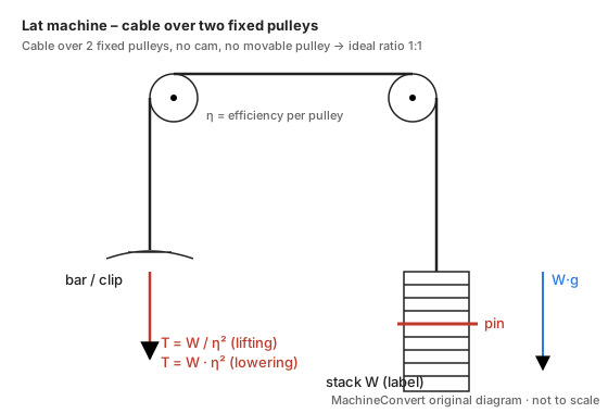
Model
T_clip = W (static) ; W/η² while lifting ; W·η² while lowering
Where the force is defined: Cable tension at the clip (bar removed). The bar's own weight helps the user and is NOT included (its mass is not published).
Inputs
| Symbol | Input | Value | Status | Uncertainty | Source (verbatim quote) |
|---|---|---|---|---|---|
| W | Selected stack label Note: Plate increments are not published; the model holds for any label. |
— | ⚙️ user setting | — | manufacturer_page: “90 kg | 198 lbs” — Standard stack; the same page lists 130 kg | 287 lbs as the increased stack · retrieved 2026-10-17 |
| R | Cable ratio How to measure: Check: bar travel = stack travel (R should be 1.00). |
1 | ✅ sourced | ± 0 — Figure shows two fixed pulleys and the bar clip on the cable end, no movable pulley → exactly 1:1 if the figure matches the machine | manufacturer_manual p. 68 (Fig. 67): “2.8.12 MNLC- LAT MACHINE Fig. 67” — Figure read by us: stack → rear top pulley → front top pulley → bar clip on the cable end. SELECTION 700 Technical Service Guide Rev. 2.0 (Technogym document, read on the easymanua.ls mirror). The "doubling pulley" section (p. 213) lists MNAC, MNDC, MNEC, MNFC, MNGC, MNHC, MNKC, MNNC – not MNLC. · retrieved 2026-10-17 |
| n | Pulleys between stack and clip | 2 | ✅ sourced | — | manufacturer_manual p. 68: “2.8.12 MNLC- LAT MACHINE Fig. 67” — Figure read by us: 2 pulleys at the top of the frame · retrieved 2026-10-17 |
| η | Efficiency per pulley | — | ✅ sourced | [0.96 … 1.0] — 0.96 (bronze bushing) to ideal 1.0; crane wire-rope data, applied to gym pulleys as an approximation | engineering_reference: “Ratio A Bronze Brushed Sheaves | Ratio B Anti-Friction Bearing Sheaves | Number of Line Parts … .96 | .98 | 1” — Table header and first row (1 line part) · retrieved 2026-10-17 |
Resulting handle-force curve
Same value at start, mid and end of the ROM (no cam/lever in this model). kgf = kilogram-force.
| Stack label (kg) | Nominal (static, kgf) | Low (lowering) | High (lifting) |
|---|---|---|---|
| 10 | 10.0 | 9.2 | 10.9 |
| 20 | 20.0 | 18.4 | 21.7 |
| 30 | 30.0 | 27.6 | 32.6 |
| 40 | 40.0 | 36.9 | 43.4 |
| 50 | 50.0 | 46.1 | 54.3 |
| 60 | 60.0 | 55.3 | 65.1 |
| 70 | 70.0 | 64.5 | 76.0 |
| 80 | 80.0 | 73.7 | 86.8 |
| 90 | 90.0 | 82.9 | 97.7 |
Error band = worst case over every input band (corner enumeration), friction applied against the motion.
Not modelled (known unknowns)
- Guide-rod friction of the stack
- Real mass of the stack plates vs. label (top plate / selector rod included or not)
- Weight of the bar (lowers the felt load)
Validation by Maxime
Follow docs/protocole-mesure-fr.md. Then compare force-gauge readings with the table above: a reading outside the band means the model (or a source) is wrong.